|
|
|
Program description Calculation-Program for HAZ cast-in-channels: FIX-CCP
|
|
Content
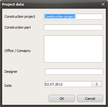
1 Project administration 2 Channel and bolt 2.1 Stand of installtion 3 Concrete, Concrete dimension 4 Reinforcement 5 Additional reinforcement for tension 6 Additional reinforcement for shear 7 Loads 8 Result 1 Project administration Click pencil icon to input project data
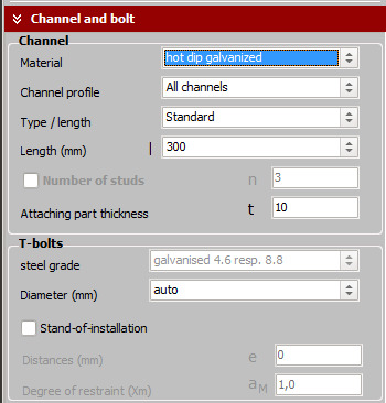
Building project: Building component: Office/ Company: Editor: Date: is set, can be changed + = Add position - = Delete position No. of items: The numbers of items are not registered in a part list 2 Channel and bolt Material of channels: Steel hot dip galvanized or stainless steel
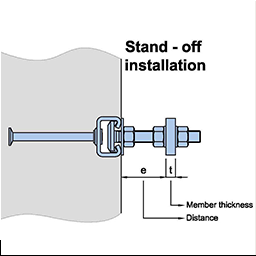
Profile: here either galvanized or stainless steel profiles are offered depending on the choice of material auto or All channels = All profiles are calculated and shown in the result image Type = Selection zwichen standard lengths and special lengths (User defined) Length: Depending on the type selection, select either standard length or special length can be input Number of anchors (studs): Only when selecting "User defined", the number of anchors can be input Number of anchors: If number of anchor unrealistic the program calculates the best number of anchors Attaching part thickness: This value is needed for choice of screw length and if input a load distance (Stand of installation) Screws Material: Slection between galvanized and stainless steel (is already set) Diameter: auto = The program selects the smallest possible diameter for the corresponding grade Stand of installation e = clear distance between the connecting part (angle, etc.), and concrete front
t = Thickness of connecting part (angle, etc.) alpha M = Rotation factor of attachmends, between 1,0 and 2,0. 1,0 = no restraint, free rotation, Input 1 The bending moment of the screw is: M = Vy*(e+t/2)/1 2,0 = complitly restraint, no rotaion Input 2 The bending moment of the screw is: M = Vy*(e+t/2)/2 The program determines the load capacity of the screw considering the shear load and bending moment. If the load capacity of the screw not sufficient, you can increase the diameter of the screw or take a higher grade of steel quality. 3 Concrete, Concrete dimension Concrete, Concrete cover
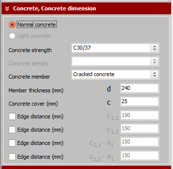
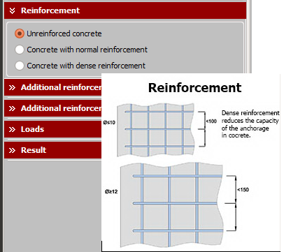
Normal concrete: At the moment you can only choose normal concrete Concrete grade: Selection of concrete grades Base concrete material: Selection between cracked and uncracked concrete Thickness of concrete d: Input in mm Conrete cover c: Inpit in mm Edge distance C1.1 und C1.2: Edge distance in the cross direction of the anchor channel (top and bottom) Edge distance C2.1-x1 und C2.2-x1: Edge distance in the longitudinal direction of the anchor channel (left and right) Edge distance C2.1 bzw. C2.2 is the calculated center distance for the first and last anchor Input here only the edge distance at each end of the anchor channel (C2.1-x1) bzw. (C2.2-x1) The edge distances are shown in the screen output in right scale If a edge distance is not input (not checked), in the output this edge is shown as dashed line. 4 Reinforcement Unreinforced concrete: Concrete without reinforcement
Normal reinforced concrete: Surface reinforcement with bar spacing ? 150 mm Densely reinforced concrete: Surface reinforcement ? 12 mm with bar spacing ? 100 mm Densely reinforced concrete: The tension resistance of an anchor is reduced only when hef is lesser than 100 mm and only in densely reinforced concrete: with factor 0,5 *hef/ 200 (≤ 1,0) 5 Additional reinforcement for tension If additional reinforcement available than
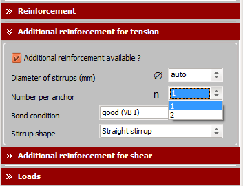
Diameter of stirrup: You can select the diameter of stirrup bar Number per anchor: You can choose 1 or 2 stirrup next to the anchor (stud) Bond condition: You can choose good or moderate bond condition (like Eurocode 2) Stirrup shape: You can choose straight or hooked stirrup ends 6. Additional reinforcement for shear The program differs between 4 cases
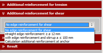
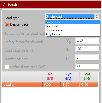
First, the characteristic resistance of a single anchor is determined: V0Rk,c = alpha-p * Square(fck,cube) * c1.1^1,5 1. No edge reinforcement for shear here is calculated with alpha-p value for cracked concrete without edge reinforcement and without stirrups (see ETA-13/0399 Annex 13, Table 4 - or additional IFBT expert report). For example for 38/17-hdg is alpha-p = 2,5 or 4,0 2. straight edge reinforcement >=12mm here is calculated with alpha-p-value for chracked concrete with straight edge reinforcement >=12mm see ETA-13/0399 Annex 13, Table 4 - or additional IFBTexpert report) For example for 38/17-hdg is alpha-p = 3,0 or 4,8 3. with edge reinforcement and stirrups with distance a lesser than 100mm here is calculated with alpha-p-value for chracked concrete with straight edge reinforcement and stirrups with distance lesser than 100 mm (see ETA-13/0399 Annex 13, Table 4 - or additional IFBTexpert report) For example for 38/17-hdg is alpha-p = 3,5 or 5,6 4. Calculation additional reinforcement on anchor here is calculated according CEN/TS-4-3 Abs. 6.3.2. The additional reinforcement is calculated for bearing all applied shear loads. The additonal reinforcement can be chosen by numbers of stirrups per anchor (1 or 2) and diameter and stirrups with straight end or angled end. The program calculated the minimum length of stirrups (lb,net acc. EN 1992-1-1). Requirement is that the required strap length can be accommodated in the concrete cross-section, otherwise the user receives an appropriate reference. 7. Loads The loads are refered as disign loads (factored loads). It is also possible to input the loads as real loads (without factor), separated in permanent loads and non permanent loads with separated different safety factor.
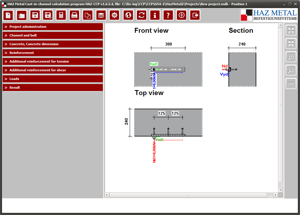
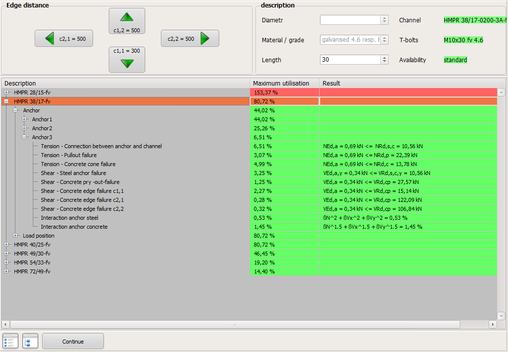
Thre are 4 different load types 1. Single load Tension load and shear load are input separated It isn´t possible to input the load position. The program determines the most unfavorable load position by shifting over channel length from left anchor to the right anchor. The screws can be fixed from the left end anchor to the right end anchor, in the overhang x=25mm (bzw. x=35 mm for profile 54/33 und 72/49) screws should not be placed. 2. Load pair Input for load pairs only half loads in kN (again separated in tension loads and shear loads). Additional input for load distance a in mm. It is assumed that the total load is applied uniformly over two screws in the anchor channel. Unequal loads must be input in load type "Any loads". Again, the worst load position is searched by shifting over the channel from left end anchor to right end anchor 3. Continuous loads Here, the load can be input if the loads are equal and always have the same distance to each other. Again, the worst load position is searched by shifting over the channel from left end anchor to right end anchor. 4. Any loads Input up to 50 loads are possible which have different load sizes and different distances. For each load, the tensile load, the shear load and the load position x (mm) is input. x is the load distance from the left end edge of channel. For this type of load the shift range can be defined, that is, to move the load from the x-position shifting in an sliding area. For example sliding area = 50 mm: The load is moving 50 mm left and right from the x-position. Is slide area not hooked, the worst load position is searched over length of channel from left end anchor to rigth end anchor. Loads in longitudinal direction The program can´t consider loads in longitudinal direction. Please contact us if you want to add loads in longitudinal direction. 8. Result After pressing the "Result" button, the result is carried out and switched to the resulting screen. First only the overall result is shown in% of capacity The overall results can be opened as a directory with subdirectories. In the subdirectories you will find the individual results of each result From the result screen you can go back with button "Next" The whole calculation result can then be printed on the screen Either as a short text (F2) Or as a long text (F3) The text can be printed out as a PDF or with a paper printer 
|
|
Program description Calculation-Program for HAZ cast-in-channels: FIX-CCP
|